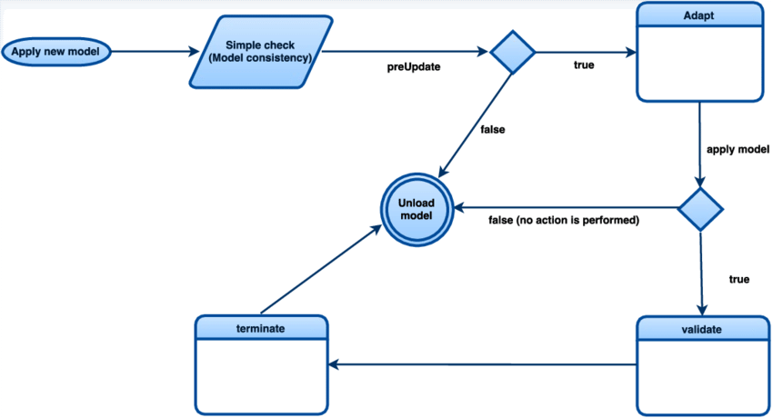
State Transition Diagram:- A state transition diagram is a way of describing the time-dependent behavior of a system.
System State
A state is an observable mode of behavior of the system.
> STD is used to develop an essential model of the system A model of how the system would behave if ew had perfect technology.
> One aspect of perfect technology is that our computer operates infinitely quickly. ‘ So any processing or computation that the system has to do, or any action it has to take will be done in zero time.
> System states can only correspond to a period of time because it waits for something in the external to occur or wait for the current activity to change in some other activity.
> Thus state represents some behavior of the system that is observable & that lasts for some finite period of time.

State Transition Diagram Notation
There are a variety of notations for STDs. A common one is given below showing the behavior of a typical telephone answering machine.
A system that existed in only one state is called a static state.
A system that does not exist in only on the estate is called dynamic state.
How a system changes its state depends on the system having orderly rules that govern its behavior. A system can have many state changes but only some of them will be meaningful & valid.
> We can show the valid state changes on our STD by connecting the relevant pair of states with an arrow.
> Fig shows that the system can change state from state 1 to state 2 and from state 2 to state3. But not from directly state 1 to state 3. A system can change directly from state 3 back to state 1.
> A system can have one initial state & one final state.
> A system can have one initial state & multiple final states but the final states are mutually exclusive meaning that only one of them can occur during any one execution of the system.
Condition & Actions
Condition
A condition is some event in the external environment that causes a change of state.
Actions
That the system takes upon its change state.
Actions are either responses sent back to the external environment or they are the calculations whose results are remembered by the system in order to respond to some future event.
Partitioned Diagram
In a complex system, there may be dozens of distinct system states & it will be difficult to show all of them in a single diagram. So to break their complexity we use a partitioned diagram or partitioning with STDs.
Steps for Building the state transaction Diagram
1. Identify all possible system states & representing each state in a separate box.
2. Select the state with normal behavior.
3. Specify the condition that makes a transition.
4. Specify the actions to produce the observable behavior in the destination state for each transition.
5. If the system is complex, partition the diagram in several STDs/.